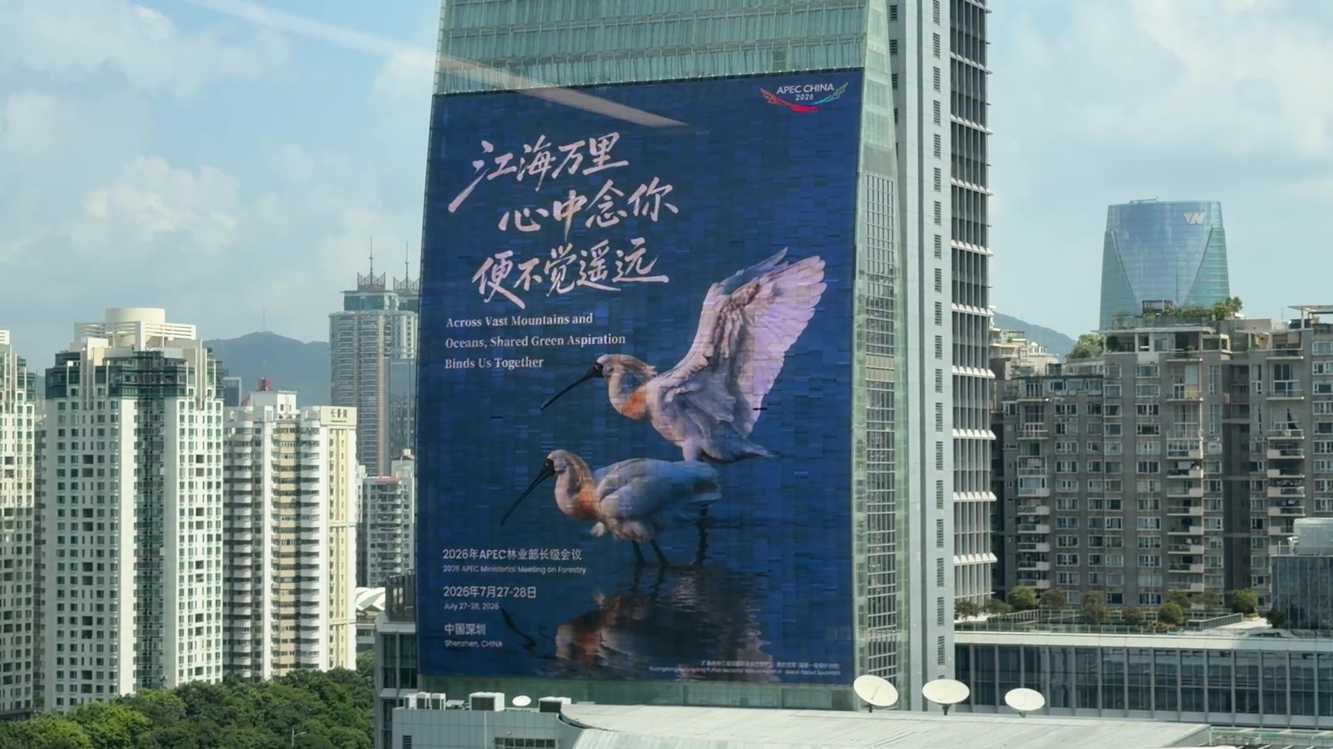
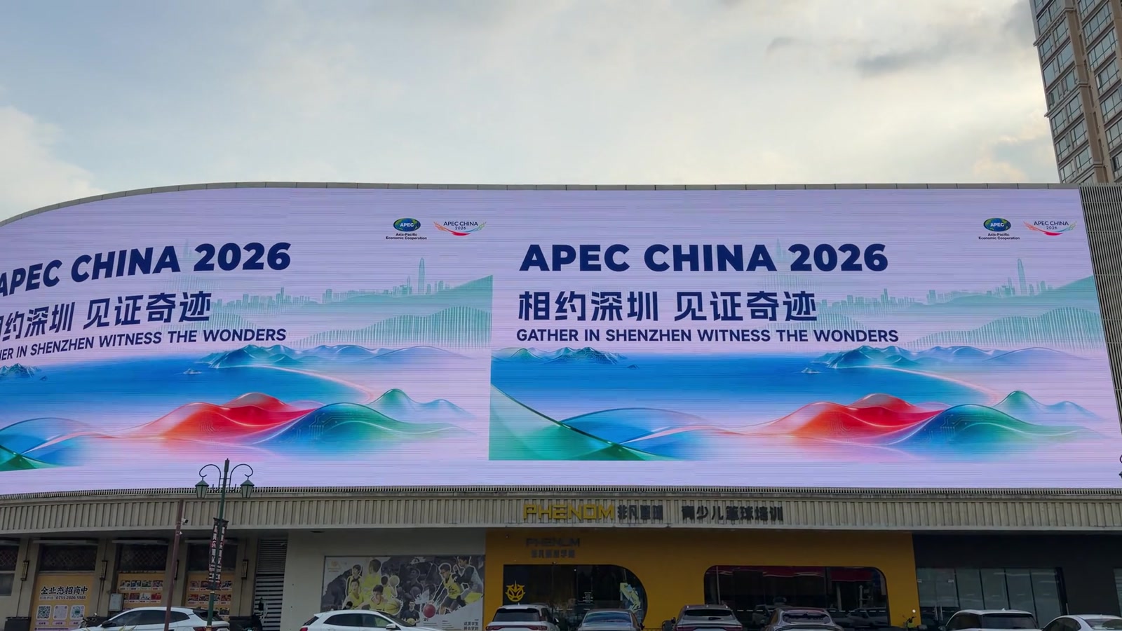
Application viewLarge outdoor LED facade showing readable full-screen public content at street viewing distance

Readability on a real LED facade

Message scale, contrast and dwell time are reviewed on the actual large-format surface.

LED content validation set

TestFiles and review method
TypographyProject-specific sizes, weights, strokes and full messages reviewed from required sightlines
MappingDiagnostic grid from creative canvas through transport raster and processor mapping to physical pixels
MotionSlow, medium and fast sequences checked for judder, detail loss and distraction
BrightnessDay, night and event presets reviewed in the actual ambient condition
CameraSpatial moiré and temporal banding tested separately with the production camera workflow

The correct LED content brief starts with the installed wall, not with a standard 16:9 video preset. Cabinet layout and pixel pitch create a physical pixel matrix. The player and processor may carry that image inside a different transport raster. Scaling, cropping and mapping then determine which source pixels reach which physical LEDs.

If those stages are not documented, a file can look correct in the studio and fail on site through unexpected crop, softness, missing edges, distorted geometry or unreadable text.

Design the full path from master composition to physical pixels, then approve typography, motion, brightness and camera behavior on the released system.

Distinguish four different canvases

An LED project can contain four related but different image spaces.

Physical pixel matrix

This is the number of addressable pixels created by the released module and cabinet layout. For example, an architectural wall may be wide, square, curved or irregular rather than 16:9.

Creative master canvas

This is the working composition used by the content team. Ideally it matches the physical matrix one-to-one. In larger or multi-surface systems, it may form part of a coordinated master canvas.

Transport raster

This is the signal carried from the player or media server to the processor: for example, a standard UHD or another supported output format. A smaller physical canvas may occupy only a defined region inside it; a wide wall may be split across multiple outputs.

Processor and cabinet map

The processor maps regions of the input raster to output ports, receiving cards, cabinets and modules. It may crop or scale before the image reaches the wall.

The released content brief must show all four. “The wall resolution is 512 × 512” is not enough if the player sends 1920 × 1080 and the processor expects the square image at a specific input coordinate.

Release a diagnostic pixel map

The pixel map should include:

  • total physical matrix and aspect ratio;
  • cabinet and module boundaries;
  • active, masked and architecturally cropped areas;
  • source-output and processor-input raster;
  • exact input coordinates for each wall region;
  • processor output and port allocation where useful;
  • protected edges and service seams;
  • orientation and content origin;
  • any curvature, corner or multi-plane transition;
  • test-pattern version and configuration owner.

Add a one-pixel grid, numbered corners, coordinate markers, circles and text labels. Display it on the actual wall before content production is locked. This detects transpose, crop, duplicate, missing-line and aspect-ratio errors faster than a brand film.

Configuration backups and the approved pixel-map file should carry the same revision reference.

Keep scaling ownership explicit

Scaling can occur in the player, operating system, switcher, processor or receiving configuration. Multiple uncontrolled scaling stages reduce predictability and can damage fine text and line work.

Record:

  • which device outputs the transport raster;
  • whether the application renders at native or scaled resolution;
  • which device performs the intentional scale or crop;
  • whether aspect ratio is preserved;
  • the interpolation and overscan settings where exposed;
  • how non-integer scaling is reviewed;
  • what happens when an unexpected input format appears.

For pixel-critical content, prefer a controlled one-to-one path for the final mapped region. When scaling is necessary, approve it with diagnostic graphics and the smallest important text — not only with photographic video.

Treat viewing-distance formulas as orientation tools

Pixel pitch influences how the pixel structure is perceived, but it does not produce one universal acceptable viewing distance. Planar’s published guide explicitly notes that acceptable viewing distance is subjective and depends on eyesight, application and content.

Use pitch-based formulas to shortlist configurations, then validate the actual messages from the real audience positions. A wall acceptable for large cinematic imagery may be unsuitable for small operational data at the same distance.

Define at least:

  • nearest possible viewer position;
  • nearest intended working position;
  • primary audience zone;
  • farthest position where information must still be read;
  • oblique and moving sightlines;
  • camera positions if the wall will be recorded.

The acceptance criterion is not “meets the pitch rule”. It is that the required content performs from the defined positions.

Build a typography test for the project

There is no universal minimum LED type size. Character height, font design, stroke width, pitch, viewer distance, contrast, message duration and visual noise all interact.

Create a project-specific type strip containing:

  • the actual brand and UI fonts;
  • multiple capital and lowercase heights in physical pixels;
  • regular, medium and bold weights;
  • thin horizontal, vertical and diagonal strokes;
  • positive and reversed text;
  • the real foreground and background colors;
  • numbers, punctuation and critical symbols;
  • full representative messages, not isolated words.

Review it from each required sightline. Record which combinations are approved, conditional or rejected. The test sizes are diagnostic steps, not a published universal rule.

For public information, test the full reading task: line length, hierarchy, dwell time and competing motion. A headline that can be deciphered eventually may still fail if a passenger has only a few seconds to see it.

Design contrast with the operating brightness

Content color cannot be approved independently of wall calibration and ambient light. The same RGB values can look different after changes to brightness preset, color temperature, gamma, low-brightness processing or module calibration.

Define representative modes such as day, night, event, broadcast or control-room operation. For each mode, test:

  • critical text contrast;
  • dark-detail separation;
  • highlight clipping;
  • saturated brand colors;
  • neutral gray balance;
  • gradients at normal and reduced brightness;
  • adjacent module uniformity;
  • reflections or ambient wash where relevant.

If the system is specified against a contrast or image-performance requirement, use the agreed measurement method and environment. A content screenshot cannot verify installed contrast.

Use motion that survives the physical scale

Large LED surfaces magnify camera movement, particles, fine textures and compression defects. Motion that feels moderate on a laptop can become uncomfortable across a wall several meters wide.

Prepare stress scenes with:

  • slow, medium and fast pans;
  • horizontal, vertical and diagonal movement;
  • scrolling type at intended speeds;
  • fine particles and high-frequency textures;
  • frame-rate conversions if they exist in the signal path;
  • cuts between dark and bright scenes;
  • long gradients and low-light motion;
  • the final codec and bitrate.

Review from the audience path, not only from the control position. Approve frame rate and motion treatment together with the playback and processing chain.

Separate moiré from temporal banding on camera

Camera-facing LED requires two different diagnostic tracks.

Moiré and spatial aliasing

Moiré is a spatial interaction between the LED pixel structure, camera sensor sampling, lens, focus, aperture, distance and angle. It may change when the camera moves, the lens changes or focus shifts. Increasing a commercial refresh-rate number does not solve spatial moiré.

Flicker, scan lines and rolling bands

These are temporal interactions involving LED scan and PWM implementation, processor timing, output frame rate, camera shutter, sensor readout, genlock and phase. A wall can be genlocked and still require phase or shutter adjustment. Two products with the same advertised refresh figure can behave differently.

Brompton’s ShutterSync and synchronization tools are examples of processor- and receiver-dependent functions for compatible Tessera systems. They must not be presented as generic capabilities of every LED processor.

The camera test should record:

  • wall product, receiver hardware and configuration;
  • processor and firmware;
  • source raster and frame rate;
  • genlock reference and phase settings;
  • camera body, sensor mode, lens, distance and angle;
  • frame rate, shutter speed/angle and exposure;
  • wall brightness and content test file;
  • observed spatial and temporal artifacts separately.

Approve the intended camera package or a defined range. “Camera-friendly LED” is not a measurable acceptance statement.

Test the full playback path

Do not assume that a player capable of 4K video can render the required wall canvas, codec, HTML composition or multi-output geometry reliably. Verify:

  • maximum decoded and rendered raster;
  • frame rate and codec profile;
  • alpha, web or real-time rendering if required;
  • output count and synchronization;
  • color format and range;
  • scheduling and transition behavior;
  • offline playback and restart;
  • processor input compatibility;
  • sustained playback with final files.

For very wide, tall or irregular systems, document whether content is created as one master, split into synchronized outputs or rendered by a media server. The operational team should not have to rediscover the mapping for every campaign.

Deliver a reusable LED content package

Provide:

  • physical matrix and dimension drawing;
  • approved pixel map and transport-raster template;
  • cabinet boundaries and protected zones;
  • source and export specifications;
  • typography and icon test results;
  • day/night or application brightness presets;
  • color and gradient test files;
  • motion and compression stress files;
  • camera workflow and approved settings where applicable;
  • player, processor and mapping configuration references;
  • naming, versioning, scheduling and approval workflow;
  • owner for future campaign validation.

This turns content production from guesswork into a repeatable system process.

Acceptance checklist

Before release, verify that:

  1. the full source-to-pixel map is documented;
  2. one device owns each intentional scaling or crop operation;
  3. critical messages are readable from all required positions;
  4. typography was approved on the actual wall or representative sample;
  5. brightness and content grades were approved together;
  6. final files were tested through the released player and processor;
  7. spatial moiré and temporal banding were diagnosed separately;
  8. camera acceptance used the production camera workflow where required;
  9. all templates, configurations and test results are revision-controlled.

Primary references

Scope note

Typography, motion, mapping and camera procedures in this article are VITREVIA project guidance. Acceptance values must be established for the actual wall, processor, player, environment, sightlines and camera package.

Project checklist

Related product and project pages