LED specification matrix

AreaParameters to release
ImageActive dimensions, pixel matrix, pitch, brightness, grayscale and calibration
TimingInput frame rate, refresh implementation, scan, latency and camera synchronization
MechanicalModule and cabinet geometry, structure, curvature and tolerance
ServiceFront or rear access, replacement unit, calibration workflow and spares
InfrastructureProcessor, signal topology, power distribution, redundancy and thermal load

Pixel pitch is one geometric input and does not define an LED system specification. Two walls with the same pitch can have different pixel matrices, optical surfaces, driver and scan architectures, low-brightness behavior, processors, power systems, structures, service methods and camera performance.

A pitch-only RFQ invites quotations that look comparable in a spreadsheet but represent different systems. The stronger approach is to define the application and acceptance evidence first, then allow bidders to propose a released configuration that meets them.

The central question is not “What pitch can you offer?” It is “What image, mechanical and operational performance must this installation deliver, and how will the proposed system prove it?”

Begin with application geometry

Define:

  • visible width, height and shape;
  • flat, faceted, curved, corner or irregular geometry;
  • nearest, primary and farthest viewing positions;
  • audience movement and oblique sightlines;
  • required image and information tasks;
  • architectural datum and permitted depth;
  • camera positions and lens ranges where applicable;
  • access zones and surrounding finishes.

Then evaluate pitch, cabinet/module geometry and total pixel matrix together.

Pitch is the center-to-center spacing of adjacent pixels. The final matrix depends on the active dimensions and released module/cabinet layout. A nominal wall size divided by pitch may not equal an available configuration because modules and cabinets come in fixed increments.

Request both the physical drawing and exact addressable matrix. “Approximately 4K” is not a mapping specification.

Use viewing-distance rules as a shortlist, not acceptance

Simple pitch-to-distance formulas are useful for early orientation. They do not decide whether a real image or message is acceptable. Planar’s viewing-distance guidance explicitly notes that acceptable viewing distance is subjective and depends on eyesight, application and content.

For each key position, define the task:

  • cinematic imagery;
  • presentation text;
  • operational data;
  • wayfinding or public information;
  • close inspection;
  • camera capture.

Then test representative content on the proposed pitch and product. A configuration suitable for large video may not resolve small data labels. A finer pitch may add cost and power without meaningful benefit at the actual distance.

The acceptance criterion should identify the content and viewing position, not merely cite a generic pitch rule.

Specify ambient-light and contrast performance

Maximum brightness is not the same as usable image quality. The system must create appropriate contrast in the installed environment while preserving dark detail, color and comfortable viewing.

Define:

  • ambient-light conditions by operating mode;
  • direct or reflected light on the wall;
  • target operating brightness, not only product maximum;
  • day, night, event or broadcast presets;
  • black-level and contrast expectations;
  • surface reflection and glare constraints;
  • required color temperature and gamma/EOTF approach;
  • measurement method, position and test pattern where numerical acceptance is required.

AVIXA’s current published standards include an image-system contrast standard. Use an agreed standard or project method where measured contrast matters; do not infer installed contrast from LED maximum brightness alone.

High maximum luminance can be useful outdoors, but it creates power, thermal and lifecycle implications. Indoors, the ability to maintain uniform color and grayscale at reduced brightness may matter more.

Require low-brightness image evidence

LED displays can behave differently when dimmed. Driver implementation, scan, PWM, grayscale processing, calibration and selected brightness preset affect gradients, color stability, flicker and dark-detail reproduction.

Request and test:

  • grayscale and color bit depth with the stated processing chain;
  • smooth ramps at normal and minimum operating brightness;
  • near-black separation;
  • low-level color neutrality;
  • module-to-module uniformity;
  • motion through dark gradients;
  • behavior after warm-up;
  • brightness-preset recall and consistency.

Do not accept a bit-depth figure without understanding whether it describes source processing, internal calculation or visible output under the quoted configuration. Evidence on the proposed wall is more useful than an isolated large number.

Separate input frame rate, refresh and scan

These terms are often collapsed into one headline figure.

Input or output frame rate describes the cadence of complete video frames in the signal path, such as 50, 59.94 or 60 frames per second.

LED refresh/PWM implementation describes how frequently and in what pattern the emitters are driven to create brightness and grayscale.

Scan architecture describes how groups of rows or pixels share drive time and circuitry. It affects the temporal pattern that a camera sensor may capture.

A published 3840 Hz or 7680 Hz value does not fully describe on-camera performance. Request the driver IC, scan ratio, receiving hardware, processor, firmware, operating brightness and test condition for the released product.

If the application is camera-facing, make the camera test contractual rather than relying on “high refresh” language.

Define color and calibration as a lifecycle

Initial factory calibration is only the beginning. Define:

  • target color space and white point;
  • processing bit depth and color pipeline;
  • per-module or per-pixel calibration method;
  • storage location and backup of calibration data;
  • uniformity acceptance at relevant brightness levels;
  • post-installation calibration scope;
  • recalibration schedule or trigger;
  • replacement-module matching process;
  • approved instrument and operator responsibility.

Ask how the system behaves after a module, receiving card or processor is replaced. A spare that lights up but remains visibly different has not restored the image system.

For color-critical and camera work, test skin tones, saturated colors, neutral grays, low-level gradients and the intended camera transform through the full chain.

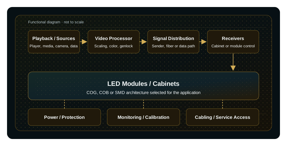
Specify the processor and receiving architecture

The processor is part of the display system, not a generic accessory. Define:

  • supported input formats and maximum raster;
  • scaling, crop and multi-window requirements;
  • output capacity with design margin;
  • receiving-card model and port topology;
  • configuration and mapping workflow;
  • color, gamma and calibration controls;
  • synchronization and genlock where required;
  • monitoring, logging and alarms;
  • configuration backup and restore;
  • API, control and preset requirements;
  • firmware ownership and rollback;
  • redundant inputs, processors, data paths or receivers where required.

Brompton’s genlock and ShutterSync are examples of capabilities available in compatible Tessera configurations. They should be specified only when the proposed processor, receiver and LED product support the required feature. Do not generalize a function from one platform to all LED controllers.

Design camera performance as a testable workflow

Camera-facing LED combines spatial and temporal risks.

Spatial risks include visible pixel structure and moiré, affected by pitch, camera sensor, lens, focus, aperture, distance and angle.

Temporal risks include flicker, scan lines and rolling bands, affected by scan/PWM implementation, receiver configuration, processor timing, frame rate, shutter, sensor readout, genlock and phase.

The specification should state:

  • camera bodies and sensor modes;
  • lens and distance range;
  • capture frame rates and shutter range;
  • source frame rate and processor output mode;
  • genlock reference and phase-control requirement;
  • wall brightness range;
  • content test set;
  • permitted and rejected artifacts;
  • test stage and witness;
  • configuration record.

Do not use one still photograph as camera acceptance. Test static and moving cameras, dark and bright content, gradients, fine texture and the required production settings.

Engineer power from operating modes

Request typical and maximum power with clearly stated test conditions. Define:

  • product maximum and calculated system maximum;
  • representative operating power at approved brightness/content;
  • power-supply efficiency and loading policy;
  • circuit distribution and phase balance;
  • inrush and startup sequencing;
  • protection, isolation and grounding/bonding;
  • cable and connector ratings;
  • heat load delivered to the room or enclosure;
  • metering and monitoring;
  • power redundancy and its actual failure boundary.

“Redundant power supplies” is not a redundancy architecture. The specification must show independent feeds, distribution, supplies and loads as applicable, then identify remaining single points of failure.

For outdoor and enclosed systems, calculate thermal behavior under the worst credible ambient, solar load, content and partial-failure condition. A maximum-brightness test in a cool factory does not approve a sun-exposed installation.

Specify structure, tolerance and service access

Image quality depends on mechanical alignment. Define:

  • supporting structure and accountable engineer;
  • total mass and service loads;
  • structural datum, adjustment and survey method;
  • cabinet/module flatness and alignment tolerance;
  • seams, corners, curvature and transition details;
  • front, rear or mixed service route;
  • removal tools and clearance;
  • access to power, data and processing components;
  • ventilation and fire-stopping interfaces;
  • cable management and strain relief;
  • surrounding finish sequence;
  • safe lifting, replacement and work-at-height method.

Front-service modules do not make the whole system front-serviceable if power supplies, receiving hardware, distribution or structure remain inaccessible.

Prototype critical corners, curves and architectural interfaces. Do not assume a flat sample proves a faceted or curved wall.

Define the environmental assembly

For indoor, outdoor, transport, industrial or public-access installations, specify the full environmental boundary:

  • operational and storage temperature;
  • humidity and condensation;
  • water and dust exposure;
  • salt, pollution or chemical exposure;
  • solar radiation and UV;
  • wind and structural loads;
  • vibration or mobile use;
  • impact and public contact;
  • cleaning method;
  • acoustic limits;
  • material and fire requirements.

An IP rating must identify the tested assembly and sides. A rated module does not automatically give the full wall, connectors, cable entries and service openings the same protection.

Model service and lifecycle cost

Compare:

  • smallest replaceable unit;
  • access time and labor;
  • spare module, power and receiver strategy;
  • calibration after replacement;
  • repair route and turnaround;
  • approved substitutions;
  • product-revision and batch compatibility;
  • firmware support and configuration ownership;
  • warranty exclusions and operating conditions;
  • expected operating schedule;
  • packaging and storage of spares;
  • documentation and training.

A lower purchase price can be offset by difficult access, large replacement units, poor spare matching or dependence on an undocumented configuration.

Ask the bidder to demonstrate a representative replacement and image recovery before final acceptance.

Build real redundancy requirements

Redundancy must start with the failure to be tolerated. Examples include:

  • loss of one source output;
  • processor failure;
  • one fibre or copper data link;
  • one sending or receiving path;
  • one power feed or supply;
  • one module or cabinet;
  • network-management loss.

For each, state the permitted visible effect, switchover behavior, alarm and recovery time. A dual input is not useful if switching is manual and the operator response exceeds the required recovery time.

Test each claimed redundant path. Diagrams alone do not prove switchover or visual continuity.

Compare bids with an evidence schedule

AreaRFQ requirementBid responseAcceptance evidence
Geometrydimensions, shape, matrix, sightlinesreleased layout and pitchdrawing review and sample/viewing test
Imagebrightness, contrast, grayscale, colorproduct/configuration valuesmeasured or witnessed test
Cameracameras, lenses, frame/shutter rangescan/receiver/processor proposalrecorded camera test
Processingraster, map, sync, control, backupnamed processor and architectureconfiguration and failure scenarios
Power/thermalmodes, feeds, heat, ambientcalculations and distributionload test and thermal evidence
Structure/servicetolerance, access, replacementdrawings and workflowfit inspection and timed exchange
Environmentconditions and assembly boundaryratings and designreports for representative configuration
Lifecyclespares, calibration, firmware, supportplan and commercial commitmentshandover package and recovery exercise

Require bidders to mark comply, comply with condition, alternative or not comply and attach the supporting evidence. This makes technical differences visible before award.

Minimum LED RFQ checklist

  1. application, audience and image tasks;
  2. physical dimensions, shape and architectural interface;
  3. viewer and camera positions;
  4. target physical matrix or content requirement;
  5. ambient conditions and operating brightness modes;
  6. contrast, grayscale, color and calibration requirements;
  7. input, processor, mapping, control and monitoring;
  8. camera frame, shutter, sync and test workflow;
  9. power, heat, distribution and redundancy;
  10. structure, tolerance, service and safe access;
  11. environment, ingress, materials and cleaning;
  12. operating hours, spares, repair and lifecycle ownership;
  13. FAT, SAT, measurement methods and handover evidence.

Pixel pitch belongs in this checklist. It does not replace it.

Primary references

Scope note

The RFQ structure and evidence schedule form part of VITREVIA’s project-development framework. Numerical acceptance limits, standards, test methods and system boundaries must be agreed for the actual application and released product configuration.

Project checklist

Related product and project pages