Integrated system deliverables

LayerReleased project definition
Player / ComputeSource files, player, OS image, CMS, codec and update method
Display controlOLED controller, LED processor or embedded display electronics
Signal and CablingInput, conversion, protection, cable schedule and connection map
InstallationStructure, glass, mounting, thermal path and service access
OperationsMonitoring, recovery, spares, acceptance record and handover

A display system is not fully defined because it powers on and shows a test image. It becomes an integrated system when the content path, control path, power path, physical installation, failure behavior and service model have all been defined, and when each function has an owner and an acceptance test.

That distinction matters commercially. A quotation for display hardware may include modules, cabinets or a controller. A system quotation must explain how the installation receives content, starts after a power interruption, reports faults, protects configuration, supports service and returns to operation after a failure.

The practical test is simple: could a different qualified team install, commission and recover the system using the released project information? If not, the project still depends on undocumented knowledge.

Start with the required outcome, not the bill of materials

Before selecting components, define what the installation must do in normal and abnormal operation.

For a retail transparent OLED showcase, the outcome may include a scheduled content loop, a controlled background, automatic start-up, remote status and front-access replacement of the playback device. For a camera-facing LED wall, it may include a defined pixel canvas, frame synchronization, calibrated brightness presets, redundant signal paths and repeatable camera settings. For a transport display, it may include vehicle power behavior, controlled boot, communications recovery and project-specific environmental evidence.

A useful system basis records:

  • application and audience;
  • visible area, viewing positions and content purpose;
  • operating schedule and expected unattended duration;
  • source types and update workflow;
  • normal, degraded and safe states;
  • environmental and installation constraints;
  • service access and maximum acceptable recovery time;
  • responsibility after handover.

This basis prevents a common failure: selecting a technically capable display and discovering later that the surrounding system cannot operate it reliably.

Map the signal, control and power paths

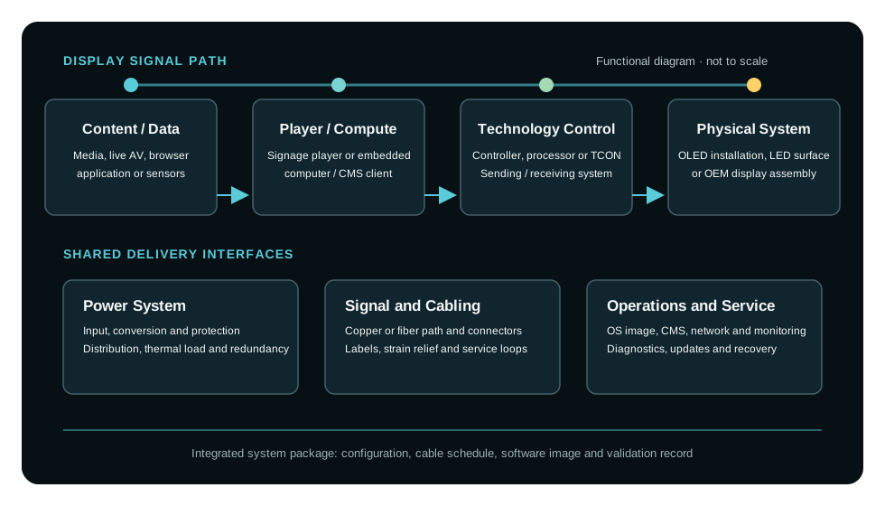
The architecture should show three paths separately.

Image and data path

The image path starts with a file, stream, browser, application, camera or data source. It continues through the player or compute platform, any distribution or conversion, the display processor or controller and finally the physical pixels.

At each interface, record the signal format, resolution, frame rate, color format, transport medium, connector, maximum verified length and ownership of scaling. For LED, distinguish the source canvas from the transport raster and the processor’s cabinet map. For transparent OLED, include the signage box or controller, display-head connection and any orientation or safe-area constraints.

“HDMI input” is not an interface definition. A released interface should state what signal is produced, what receives it and what happens when the signal disappears or changes.

Control and network path

The control path may include a CMS, device-management service, building-management interface, show control, sensors, GPIO, serial control or an API. It also includes credentials, certificates, network addressing, time synchronization, monitoring and update approval.

Do not assume the customer’s IT team owns these functions merely because they use a network. The project must assign who provisions devices, approves outbound connections, maintains certificates, receives alarms, grants remote access and authorizes software updates.

Power path

The power architecture includes the supply source, conversion, protection, isolation, distribution, sequencing, earth or bonding provisions, power budget and heat load. It should describe start-up current, controlled shutdown where required and behavior after power returns.

For redundant designs, state what is redundant and what remains a single point of failure. Two power supplies do not create end-to-end redundancy if they share one input feed, distribution branch or controller.

Define every interface before production

Most integration problems occur between components that work correctly on their own. The useful project document is therefore not only a component list, but an interface register.

InterfaceDefinition requiredTypical evidence
Source to playerfile, stream, application, data and update methodapproved test content and playback result
Player to processor/displayformat, raster, frame rate, color, scaling ownersignal-path diagram and test-pattern capture
Processor to LED/display headcontroller, receiver map, firmware, cable topologyreleased configuration backup and port map
Network to managed deviceaddressing, ports, DNS/NTP, credentials, offline behaviornetwork schedule and remote-management test
Building/vehicle power to systeminput range, conversion, protection, sequencingpower diagram and restart test
Display to structure/glassload, tolerance, datum, ventilation, cable exit, accessapproved drawing and fit inspection
System to operatorstart/stop, status, alarms, recovery and escalationoperator procedure and witnessed scenario test

Each interface should have one party accountable for providing it, one party accountable for accepting it and a revision-controlled definition. “By others” is only useful when “others” are named and the boundary is explicit.

Design abnormal states before they happen

A system that works only in its ideal state is not production-ready. Define at least the following scenarios where relevant:

  • power is lost and later restored;
  • the network is unavailable at boot or disappears during playback;
  • the source signal is missing, unstable or has the wrong format;
  • the CMS cannot be reached;
  • a player application stops responding;
  • configuration or content storage is corrupted;
  • one signal or power branch fails;
  • a temperature, fan or device alarm is raised;
  • credentials or certificates expire;
  • a replacement device has to be installed from stock.

For each scenario, specify the visible state, automatic response, allowed recovery time, remote indication, operator action and escalation path.

This exercise changes component selection. A player with adequate playback performance may be unsuitable if it cannot be reprovisioned consistently. A processor may create an unacceptable recovery path if its configuration is not backed up. A physically replaceable LED module may still be difficult to return to visual uniformity if service calibration is undefined.

Release configuration, not just hardware

The approved system is a combination of physical components and controlled configuration. Record:

  • manufacturer, model and hardware revision;
  • operating-system, firmware and driver versions;
  • player application or runtime version;
  • CMS tenant, group and publishing configuration;
  • processor and receiver-card configuration;
  • pixel map, scaling and color settings;
  • network settings and credential policy;
  • brightness presets and operating schedule;
  • monitoring thresholds and alarm recipients;
  • configuration backups and restore instructions.

An uncontrolled firmware update can change signal compatibility, color, boot behavior or management access. Version changes should therefore have an owner, a test scope and a rollback route.

Commission against requirements, not against impressions

Commissioning is more than confirming that the image looks good. AVIXA’s performance-verification framework is useful because it separates system requirements from the tests used to demonstrate them. The exact test list remains project-specific, but it should be written before site acceptance.

A display-system verification schedule can include:

  • physical installation against approved drawings;
  • pixel map, orientation, crop and source routing;
  • representative image quality at approved operating presets;
  • color and luminance checks where specified;
  • signal loss and restoration;
  • power-cycle and unattended restart;
  • scheduled and emergency content publication;
  • monitoring, alarm and screenshot functions;
  • network-loss and offline playback behavior;
  • backup, restore or replacement-device provisioning;
  • service access and safe component removal;
  • operator workflow and escalation procedure.

Record the method, instrument or test file, expected result, actual result, date and accountable witness. A photograph of a working screen is not a commissioning record for the integrated system.

Separate FAT, SAT and operational acceptance

Different risks are best tested at different stages.

Factory acceptance testing (FAT) can verify the released hardware set, representative cabling, software image, configuration, content, control logic and failure recovery before shipment. It is the right stage to find architecture and configuration defects.

Site acceptance testing (SAT) verifies the real power, network, cable lengths, physical installation, ambient conditions, viewing positions and interfaces supplied by other trades.

Operational acceptance confirms that the owner can publish content, understand alarms, perform routine operation, restore configuration and obtain support. A technically commissioned system can still fail operational acceptance if no one owns credentials, software updates or incident response.

The FAT and SAT configurations must remain traceable. If hardware, firmware, cabling or processor settings change after FAT, the affected tests should be identified and repeated.

Hand over an operable and reproducible system

The final package should enable operation, service and reproduction. Depending on scope, it includes:

  • approved system and interface diagrams;
  • as-built mechanical, signal, network and power drawings;
  • equipment and cable schedules with labels;
  • released software and firmware register;
  • configuration backups and checksums where appropriate;
  • CMS, network and access-ownership records;
  • commissioning results and open-item register;
  • operating, shutdown and recovery procedures;
  • cleaning and service instructions;
  • spare-parts and replacement strategy;
  • warranty, support contacts and escalation route;
  • change log and document owner.

AVIXA D401.01 addresses documentation requirements, while D402.02 addresses performance verification. They provide useful professional frameworks; they do not replace the application-specific requirements, manufacturer instructions or statutory obligations of a particular project.

A practical system-definition test

Before releasing a display system, ask five questions:

  1. Is every source-to-pixel, control and power interface documented?
  2. Does every interface and lifecycle function have a named owner?
  3. Are abnormal states and recovery behavior defined?
  4. Can the approved configuration be backed up, restored and reproduced?
  5. Is each critical requirement linked to an acceptance test and recorded result?

If any answer is no, the missing item is part of the system scope, even if it was absent from the original hardware quotation.

What to include in a VITREVIA system brief

Send the application, display technology or candidate product, target dimensions, viewer positions, content sources, operating schedule, building or vehicle interfaces, network conditions, service constraints, required monitoring, redundancy expectations, validation requirements, quantity, country and project stage.

VITREVIA can then define the display, playback, processing, control, power, cabling, mechanical and validation boundaries as one released system architecture.

Primary references

Scope note

The architecture, interface-register structure and acceptance sequence in this article form part of VITREVIA’s project-development framework. Project requirements, applicable standards, tests and evidence must be agreed for the actual application and released system configuration.

Project checklist

Related product and project pages