Architecture comparison
| Family | Construction | Project strengths | Engineering checks |
|---|---|---|---|
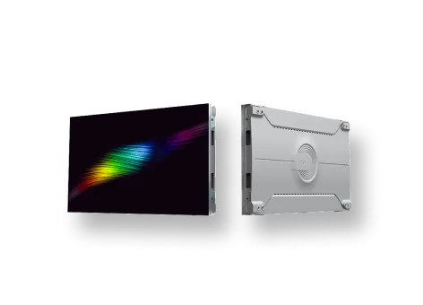
| COG | Display integration using a glass substrate | Potential thin and high-density product architectures | Released drive method, substrate format, thermal path and replacement unit |
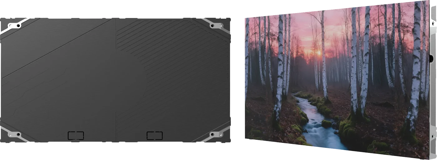
| COB | Bare LED dies bonded to a board before product-specific encapsulation | Potential fine-pitch and treated-surface product architectures | Encapsulation, reflection, protection evidence, service and calibration |
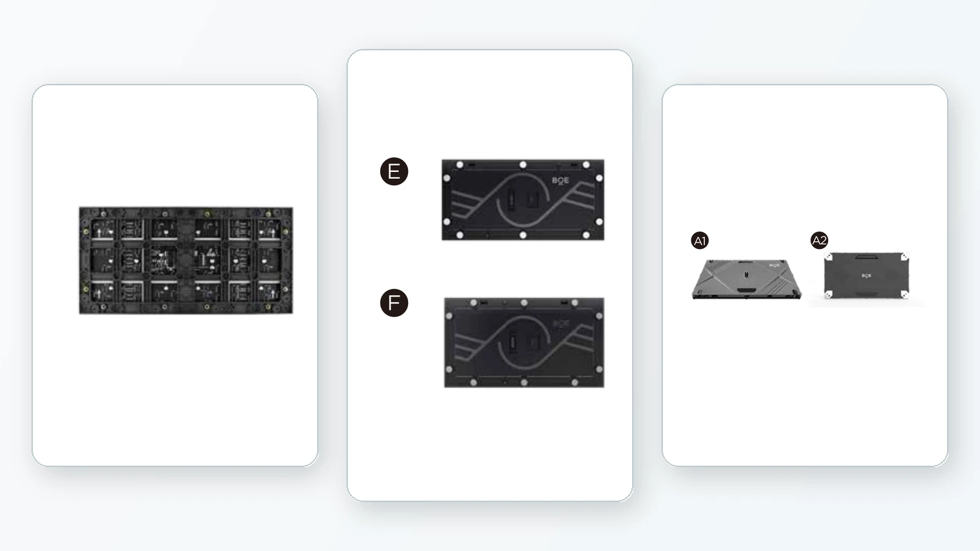
| SMD | Packaged LEDs mounted on a PCB | Multiple product-specific indoor and outdoor architectures | Package, mask, coating, scan, environmental boundary and service method |
COG, COB and SMD are not three grades on a single quality scale. They describe different parts of how an LED display can be constructed and integrated. The label alone does not determine image quality, surface protection, drive method, serviceability, camera performance or lifecycle cost.
The correct comparison has two stages:
- understand what the construction label identifies;
- compare the released products and integrated system configurations using project evidence.
A newer or more specialised abbreviation can be the right choice, but only if the supplied product meets the actual optical, mechanical, electrical, service and operational requirements.
What the labels identify
SMD: packaged emitters mounted to a board
Surface-mount device LED construction uses packaged emitters assembled onto a PCB. It appears across many indoor and outdoor products, pitches and cabinet formats.
The term SMD does not define one package size, mask, coating, ingress rating, scan architecture, repair method or visual result. Some products allow emitter- or module-level service; others are designed around larger replaceable units. Those properties must come from the released product documentation.
COB: bare dies attached and encapsulated on a board
Chip-on-board construction generally places LED dies onto a board before encapsulation. Fine-pitch products often use a treated or encapsulated front surface, but the chemistry, thickness, finish, reflection, repair route and protection performance vary.
“COB” does not automatically mean a perfectly continuous, impact-proof or field-repairable surface. The project should evaluate the actual encapsulation and service evidence.
COG: integration using a glass substrate
Chip-on-glass architectures integrate display elements and interconnects with a glass substrate. BOE’s published MLED COG products include active-matrix implementations, but active matrix should be attributed to the named platform or product — not assumed to be a universal property of every system described as COG.
COG can create distinctive thin, dense and integrated structures. It also changes the questions around substrate size, segmentation, edge handling, mounting, thermal path and replacement method.
Do not let the package label answer unrelated questions
The following characteristics cannot be inferred safely from COG, COB or SMD alone:
- pixel pitch and actual pixel matrix;
- active- or passive-matrix drive;
- scan ratio and PWM implementation;
- common-anode or common-cathode architecture;
- refresh and low-brightness behavior;
- LED wavelength and color uniformity;
- encapsulation, coating, mask and surface reflectance;
- touch, impact, moisture or contamination resistance;
- module and cabinet format;
- front- or rear-service method;
- replacement granularity and field repair;
- calibration storage and post-service workflow;
- processor and receiving-card compatibility;
- data and power redundancy;
- camera performance;
- rated environment and operating duty.
Every one of these requires released-product evidence and, where it affects the outcome, a representative sample or system test.
Compare the pixel and drive architecture
Request a controlled description of the pixel structure and drive path:
- physical pitch and pixel arrangement;
- emitter configuration and package/die construction;
- active or passive drive, if relevant;
- scan architecture and driver IC;
- receiving hardware and configuration;
- grayscale and refresh behavior at required brightness;
- module and cabinet pixel dimensions;
- available calibration data and processing path.
Do not compare headline refresh figures without the test condition and configuration. Low-brightness grayscale, scan artifacts and camera interaction may differ even when two quotations publish the same maximum refresh number.
If the manufacturer cannot identify the driver, receiver and released configuration behind the quoted value, the claim is not yet useful for engineering comparison.
Evaluate the optical surface
Surface construction affects more than protection. It influences perceived black level, ambient-light contrast, glare, color shift, viewing angle and uniformity.
Compare samples under the intended lighting using:
- display off and low brightness;
- black, gray and full-color fields;
- direct and oblique viewing;
- controlled point-source reflections;
- representative cleaning condition;
- adjacent modules and replacement modules;
- the specified mask, coating or encapsulation finish.
A glossy encapsulated surface may behave differently from a masked matte SMD product in a bright control room, even if its dark-room image appears stronger. Conversely, the same encapsulation may offer useful physical robustness for a close-access public installation. The application decides which trade-off matters.
Ask for protection evidence, not adjectives
Terms such as robust, waterproof, anti-collision, dustproof and moisture-resistant are incomplete without a test method, level, sample construction and boundary.
Request:
- published ingress or environmental rating and exactly what assembly it covers;
- impact, abrasion or surface-hardness method where relevant;
- permissible cleaning materials and procedure;
- edge and rear-side protection;
- behavior after surface damage;
- repair limitations and cosmetic acceptance criteria;
- evidence for the released pitch and product revision.
Front encapsulation does not automatically protect connectors, edges, power electronics or the rear of the module. The installed system still needs an environmental design.
Compare service as a workflow
“Front service” says only where access begins. A useful service comparison covers:
- smallest replaceable field unit;
- removal tool and clearance;
- risk to adjacent pixels or surface;
- power and data isolation procedure;
- access to power supplies and receiving hardware;
- time to exchange the unit;
- configuration or identity transfer;
- calibration after replacement;
- visible uniformity of a spare unit;
- repair location for the removed part;
- spare storage, shelf life and traceability.
COG or monolithic-style display units may require replacement of a different area than modular COB or SMD products. That is not automatically worse or better. Model the actual failure frequency, unit cost, labor, downtime and visual recovery.
Compare thermal and mechanical integration
Request the power and heat data at the intended operating preset, not only a theoretical maximum. Define:
- maximum and typical input power with test image and brightness;
- heat path from emitting surface, board/substrate and driver electronics;
- permitted module and ambient temperatures;
- cabinet ventilation or cooling;
- flatness and alignment tolerance;
- substrate and module handling limits;
- wall structure, datum and adjustment method;
- weight, depth and service loads;
- curvature capability only for the released product.
Fine pitch reduces tolerance for visible steps, gaps and color differences. A strong pixel architecture cannot compensate for a structure that cannot hold the required alignment.
Validate camera performance as a system property
No package family is automatically camera-safe. Camera performance depends on pixel pitch, optical surface, scan and PWM implementation, driver and receiver configuration, processor timing, frame rate, genlock, phase, brightness, camera sensor, shutter, lens, distance and focus.
Separate spatial moiré from temporal banding. Then test the released wall configuration with the intended camera workflow. Record firmware and configuration; changes can alter the result.
If the project is broadcast, XR or high-value image capture, require a camera test before award or make the accepted test a contractual gate.
Use a released-product evidence matrix
| Decision area | Evidence to request | Sample validation |
|---|---|---|
| Pixel/drive | pitch, pixel structure, drive, scan, driver and receiver | fine detail, gradients and low-brightness motion |
| Optical surface | finish, reflectance-related data, viewing angle, calibration | off-state, black/gray fields, ambient reflections |
| Protection | named test method, rating and assembly boundary | cleaning, handling and agreed impact exposure |
| Service | replaceable unit, access drawing, calibration workflow | timed replacement and visual recovery |
| Thermal/power | test condition, typical/max power, temperature limits | representative content at operating preset |
| Mechanics | dimensions, tolerance, mass, mounting and curvature | multi-unit alignment and service load |
| Camera | released configuration and test conditions | production camera, lens, shutter and timing |
| Lifecycle | warranty, spares, repair route, revision control | replacement-unit and configuration exercise |
The matrix should be completed for the exact quoted product, pitch, module, cabinet, receiver, processor and firmware — not for a generic technology family.
How to choose
Choose the configuration that provides the strongest evidence against the application’s actual risks.
Close-view corporate or control rooms may prioritize low-brightness image quality, surface reflections, fine-detail uniformity, quiet thermal design and precise service recovery.
Public-access installations may prioritize cleanability, touch or impact exposure, protected edges, safe removal and predictable spares.
Broadcast and XR prioritize spatial sampling, scan/PWM implementation, processing, synchronization, phase control, low-brightness color and tested camera performance.
Outdoor or high-ambient applications prioritize environmental construction, ambient contrast, brightness sustainability, thermal design and access, not simply emitter packaging.
Large rollout programs add manufacturing consistency, revision control, spare compatibility, calibration traceability and manufacturer lifecycle support.
The winning acronym is irrelevant if the product cannot satisfy the required system evidence.
Red flags in a quotation
Treat these statements as requests for more information:
- “COB is always more durable.”
- “SMD is always easier to repair.”
- “COG always means active matrix.”
- “High refresh guarantees camera performance.”
- “The front is waterproof, so the wall is outdoor-ready.”
- “Both products have the same pitch, so image quality is equivalent.”
- “Front service means there is no rear-clearance requirement.”
Each may be true for a particular released design under defined conditions. None is a safe family-level conclusion.
Primary references
- BOE MLED product platform — manufacturer platform showing COG, COB, SMD and transparent product categories with product-specific architectures.
- BOE MLED COG products — current examples of model-specific COG and active-matrix claims.
- BOE MLED COB products — current examples of model-specific COB product data.
- BOE MLED manufacturing platform — manufacturer context for the MLED platform and production routes.
- Planar MG-2COB Series — an independent manufacturer’s released COB product family, illustrating that surface protection, service format and environmental claims are model-specific.
- TCL CSOT / SID — 142-inch IGZO-TFT glass-substrate AM MiniLED display — published conference paper documenting an active-matrix MiniLED architecture on a glass substrate outside the BOE product family.
Scope note
Definitions in this article identify broad construction routes, not universal performance guarantees. The evidence matrix and decision sequence form part of VITREVIA’s project-development framework. Final selection must use the released product and integrated system configuration.
Project checklist
Related product and project pages
Direct-View LED Systems
Review current COG, COB, SMD, outdoor and creative LED product families.
Review LED SystemsQuality and Acceptance
Define the inspection and acceptance evidence for the configured LED system.
Review Quality and AcceptanceOutdoor LED Applications
Connect LED specification decisions to a real architectural application.
Explore the ApplicationRelated LED Guide
Continue with the complementary LED engineering guide.
Read the Related GuideProject Requirements
Organize geometry, environment, content, operation and service inputs for engineering review.
Build the Project Brief